Development of advanced simulation methodologies for test prediction analysis
Advanced Finite Element (FE) simulation models will be developed, which will focus on the specific issues of the stiffened panels under testing, i.e. those related to buckling and post-buckling behaviour, the damage evolution in 4th generation Al-Li and thermoplastic material systems and the integral stiffening concepts. The integral stiffening concept of the metallic panel arises from the Laser Beam Welding (LBW) or Friction Stir Welding (FSW) of the stiffening elements on the Al-Li skins (see figure below), while for the thermoplastic panel from processes, such as in-situ consolidation, bonding, welding (induction / friction), (see figure below). The FE analyses will mainly target in test response prediction required for the testing campaign preparation.
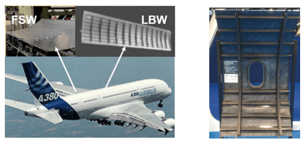 Figure: Examples of FSW and LBW in A380 (left) and Induction Welding of thermoplastic panel (right)
The complex buckling and post buckling analysis of thin-walled stiffened panels, including damage evolution, provides a good understanding of the structural performance of compressively loaded thin-walled stiffened structures under in-plane loads. The typical geometry of the panels to be tested in the present project comprises skins stiffened by bulkheads, frames and stiffeners, as indicatively shown in the figure below.
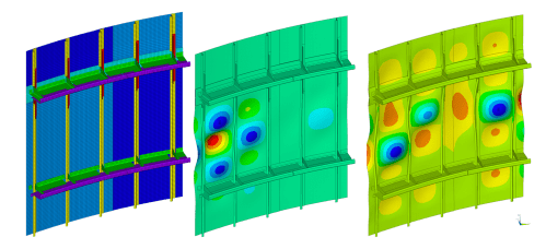
Figure FE mesh of typical fuselage stiffened panel to be modelled and tested (left); characteristic eigenvalue buckling analysis (centre); post-buckling response by geometrical non-linear static analysis.
Detailed Finite Element (FE) models of the stiffened curved panels will be developed, based initially on the theoretically perfect geometry of the CATIA drawings provided by the Topic Manager. Consequently, the real external surface geometry of the three panels to be tested will be acquired by DIC method and the FE models will be updated, to include initial panel imperfections, which are very important for buckling and post buckling analysis.
This high-fidelity modelling approach will be also applied in the description of the progressive damage evolution of metallic and composite materials up to failure. For the metallic panels, this will include prediction of crack initiation and propagation in static and fatigue loading, while for the composite panel it will comprise the different modes of ply cracking and inter-ply delamination at local scale incorporated at global level via a multi-scale approach.
Α static analysis under the combined loading, as calculated at panel level will be initially performed, in order to identify the most critical panel areas. An eigenvalue buckling analysis of the stiffened panels will follow, in order to predict the theoretical critical buckling load and mode, i.e. the load at the bifurcation point of the ideally linear elastic structure. Having gained a good understanding of the panel behaviour by static and eigenvalue buckling analysis, a nonlinear static analysis, with geometrical non-linear terms taken into account in the kinematic equations, will be performed; through the non-linear analysis a more accurate prediction of the critical buckling load will be calculated, as well as the post-buckling behaviour; it should be highlighted that prediction of panel response beyond the initial buckling regime is not possible by the eigenvalue buckling analysis. The non-linear analysis will run up to structural instability prior to the ultimate panel failure and the buckling shape will be predicted and compared to the respective experimental data for the loading cases of internal pressure and compression / shear loads independently introduced, as well as at the combination of both loading conditions.
In addition a Damage Tolerance (DT) methodology will be applied for predicting cracks initiation and growth at the actual fatigue spectrum applied on the test, in order to serve as an aid to the endurance test planning and a means of comparison with the test results.
The Damage Tolerance approach assumes an initial flaw within the component, usually of the minimum size detectable by the non-destructive evaluation method in use; for aeronautical applications, engineering cracks are assumed to be in the range of 0.75mm to 1.0 mm, which roughly corresponds to the limit of standard non-destructive inspection techniques. Based on the above rationale and the endurance material data, which will be provided by the TM for this purpose, a damage tolerance life calculation methodology for the metallic stiffened panel will be developed in DEMONSTRATE. The methodology will combine damage tolerance principles and probabilistic approaches to take into account the variability of material properties and damage characteristics to quantify the probability of failure. The methodology will comprise the modules for crack initiation, crack propagation and residual strength assessments, as indicatively shown for the metallic materials in the following flow chart:
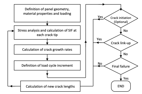
Figure: Fatigue life calculation of the Ali-Li stiffened panel based on damage tolerance approach
The damage of the thermoplastic composite stiffened panel, which has welded/bonded stiffeners and frames, may be attributed either to composite material damage or weld-line/bond-line failure. Damage in the thermo-plastic composite material will be simulated using the Continuum Damage Mechanics approach (CDM). Damage types considered will include fiber tensile/shear failure, fiber compressive failure, matrix tensile and compressive failure and delamination. In the numerical simulation, damage progression is characterized by decrease of material’s stiffness at the post-failure region.
De-bonding initiation and propagation in the interface line or the bond /weld-line (e.g. bonded / welded stiffeners and frames) will be simulated using the Cohesive Zone Modelling approach. Cohesive zone models relate tractions σ to displacement jumps (separation) δ at an interface where a crack may occur. Damage initiation is related to interfacial strength, i.e. the maximum traction σmax in the traction-displacement curve; when the area under the traction-displacement jump relation is equal to the fracture toughness Gc, the traction is reduced to zero and new crack surfaces are formed. Both bi-linear and exponential traction-separation laws will be investigated aiming to efficiently capture the physical behaviour of welded, bonded or co-consolidated thermo-plastic composite material interfaces. The parameters that are needed to calibrate the traction-separation law, i.e. interface stiffness, strength and fracture toughness will be extracted from test data provided by TM, typically comprising quasi-static mode-I tests on welded DCB specimens, quasi-static mode-II tests on welded ENF specimens and quasi-static mixed-mode tests. Images from such tests conducted are shown in the figure below.
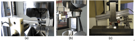 Figure: (a) DCB test on thermoplastic composite joint, (b) ENF test on a composite bonded joint, (c) Mixed-mode test on a composite bonded joint
When performing experimental tests, it is crucial to correlate them with accurate and optimized simulations. The models need to be validated due to instrumentation limits. The main issue is, nevertheless, the reliability of these simulations. In order to have these simulations, all the inputs for the model have to be correct, taking into account all the parameters. This does not only include the data of the structure (such as material properties), but also the boundary conditions of the experimental test that is to be simulated.
These boundary conditions will be obtained by Applus using its Absolute Accurate Methodology from the tests, which takes into account all the parameters of the test that can affect it, getting real boundary conditions that can then be used in the simulation.
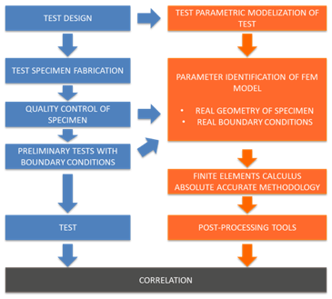
The simulations will be performed by Athena RC with the experimental data obtained by Applus in the tests being performed. By comparing the experimental results to the simulation results, the model will thus be validated.